
Performance Parts
Lotus Esprit SE
Toyota MR2
Technical Articles
Diagnostic Tools
Turbo Systems
Upgrades
John's Projects
'91 Esprit SE
'87 MR2 Turbo
WC Engineering
Service Work
News & Updates
FAQ
Contacts & Ordering
Links & Testimonials
Upgrading an Elise to a Close Ratio Gear Set
This is some information and pictures of the installation of a short ratio gear set in the S1 Elise (Rover) transaxle. This gear set is a popular upgrade for use on short to mid-length tracks. It uses straight cut gears so there is a slight increase in the "whine" of the transmission, but at a track event that really isn't an issue.
This is a very easy transaxle to work on. The most difficult part is the case disassembly. The only special tools needed are strong long nosed snap ring pliers and a 17mm Allen wrench or Allen socket. If you have access to the shop manual on the teardown it can also help.
Click on any of the photos to view a larger version.
Start with the transmission on a bench, sitting with the bellhousing facing down. Remove the speedo drive.

Then remove the small bolt that holds the reverse gear idler shaft. Once these two are out, it's on to the big plug on the rear of the case. This is a LARGE hole plug with a 17mm hex hole in it. There is a ton of thread sealant on it. You MUST use a good Allen wrench or Allen socket on it. The trick of using a bolt with a 17mm head won't work on this one.
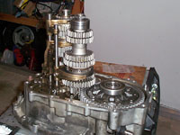
Once the plug is out, remove the bolts that hold the two case halves together. You will only be able to separate the case by a few millimeters. At this point you will need to remove the snap ring from inside the hole where the plug was. This can be difficult. You will need a pair of narrow, long, strong snap ring pliers, and possibly a long small screwdriver. While one person frees the snap ring, another person lifts the case off.
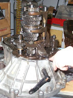
This is what you're left with.
Next, as started in the picture, is to remove the reverse linkage. There are two bolts that hold it to the case. Remove it and put it aside with the bolts. The reverse idler shaft and reverse gear can be lifted out. Note the orientation and the direction of the bolt hole.
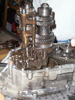
The shifter actuators are next.
Make note of the position of the springs and how they engage the shift selector shaft, then unbolt the assembly and set it aside as well.
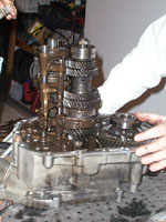
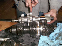
Now we have the input and output shafts, shift rails, and shift forks left.
Before we remove them we are going to "double engage" two gears. We move the 1-2 shift fork into 1st or 2nd gear then move the 3-4 shift fork into 3rd or 4th. This will lock the two shafts and keep them from turning. While they are locked we can remove the large staked nut at the end of the output shaft. Use a brass drift and hammer to pry back the tang on the nut before trying to unscrew it. (The nut will have to be replaced.)
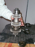
Once the nut is off, disengage the gears. The whole assembly of the input and output shafts and the shift rails is lifted from the case as a single piece.
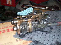
Place the assembly on a bench and remove the shift rails with forks from the shafts. They will just slide off but note their positions. The shafts are now free from each other.
Starting with the output shaft, we will move the needed parts over to the new shafts.
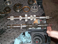
Now compare the new output shaft with the original. Here the straight gears are obvious compared to the helical cut gears. Notice the parts that will be transferred. The shift hubs and syncros will be removed from the original shaft and installed on the new shaft.
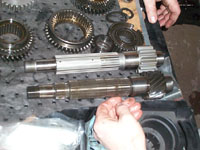
Here we see the new and original shafts.
Begin assembly of the output shaft. The gears just slip on to the shaft.
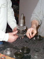
A few more gears...
And the output shaft is assembled.
Notice the reverse gear is part of the 1-2 shift hub.
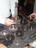
Now repeat the process for the input shaft.
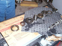
It's a good idea to lay out all the parts on a bench as you disassemble the shaft.
Transferring the input shaft parts is similar. However, on the 3rd driven gear, the bearing is different. The original shaft uses a plastic carrier to hold the needle bearings and the new shaft and bearing use loose needle rollers. Use a liberal amount of grease to hold the needles in place on the shaft, then slide third gear over the rollers. Everything else slides right on.
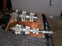
These are the finished input and output shafts.
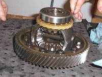
Last, change the ring gear on the differential. After the shafts and shift rails were removed, the differential assembly will just lift from the case. You may want to use an impact wrench to brake the ring gear bolts loose. Once the bolts are removed, the ring gear simply lifts off. Be sure to clean the differential seating surface and new ring gear surface before installing the new gear. Set the new ring gear on the differential and install a few bolts to locate the ring, then install all the bolts only finger tight. Using a torque wrench, tighten all the bolts in a criss-cross pattern.
Since we are not replacing the differential or bearings there is no need to adjust the final drive bearing pre-load. (NOTE: If you are installing new bearings or an LSD you MUST adjust the bearing pre-load.) Before placing the differential assembly back in the case, clean the mating surfaces of the case halves to get a good seal when reassembling the transaxle. Afterwards, place the differential assembly back in the case.
Assembly of the transaxle is the reverse of the removal. Place the input and output shafts together and install the shift forks/rails onto them, then place the whole assembly into the transmission case.
As when the transmission was disassembled, "double engage" the gears again to tighten the nut on the end of the output shaft. Remember to disengage them before you install the selector shaft linkage. When installing the reverse gear and idler shaft, note the orientation of the bolt hole. The hole in the shaft has to line up with the hole in the case. Install the reverse bracket and linkage.
Test the shifting of all the gears before installing the case half by having one person hold the shafts in place while the other person pushes, pulls, and twists the selector shaft.
Put the sealant on the bell housing mating surface of the case. (I prefer to use Toyota FIPG 00295-01281. I don't believe there is anything better in the entire world to seal a transmission case.) Then slide the case down. You may have to give the case and the shafts a "little special lovin'" to get it to drop all the way on. Once it's down, install the reverse gear idler shaft bolt. Do this first, so if it doesn't line up you can still get the case apart. Install the case bolts finger tight, then the snap ring in the bearing though the hole in the end of the case. Tighten the case bolts and put some sealant on the big hole plug and install it. Install the speedo drive gear. Check the shifting one more time and then you're ready to reinstall the transmission.
© 2009 WC Engineering LLC, Website Design by Adastra Design